(DIY) Adding a tank to compressor.

Amra

Needle-chuck Ninja
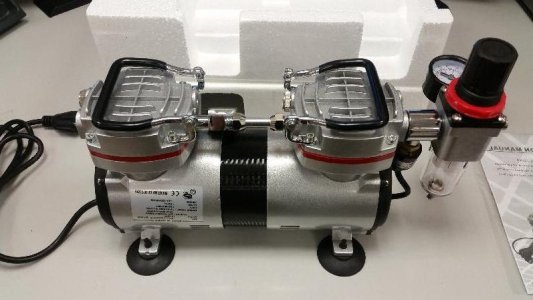
So, where to begin. For Christmas my sister got me a new compressor (This one). She knew my old one was pretty well knackered. :D
I went ahead and tried using this compressor, and it did work pretty good, however there were a couple issues that I ran into (I referenced those issues in this thread, and I felt they would be eliminated by adding a tank.

Of course the easier and less expensive option would have been to ask my sister to return the gift, and exchange it for same compressor already mounted on a tank (This compressor) Heck, the brass fittings alone will cost more than the 30 dollars difference between those two compressors!

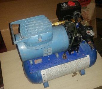
Undeterred, I decide I might as well do it myself. As I said, I already had a fairly knackered airbrush compressor that I cobbled together a while back, so I might as well recycle it!
That is my old compressor, but that is a photo for the next post.

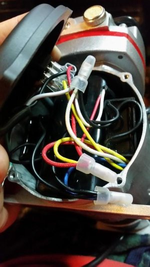
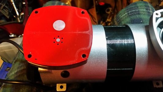
The first step was disassembling my new compressor! In order to remove the regulator assembly, check valve, and pressure sensor/switch off the new compressor, I needed to disconnect the pressure switch from the wiring, so first order of business was to open the face, and draw up a wiring diagram, then open the wiring clips to remove the wires connected to the pressure swich.
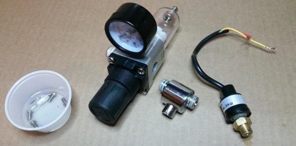
After that, I could unscrew the pressure switch, then unscrew the regulator assembly and the finally unscrew the checkvalve from the regulator.
It seems they use some kind of loctite/hardening pipedope on the threads, but they came off with some "gentle" pursuasion.:thumbsdown:

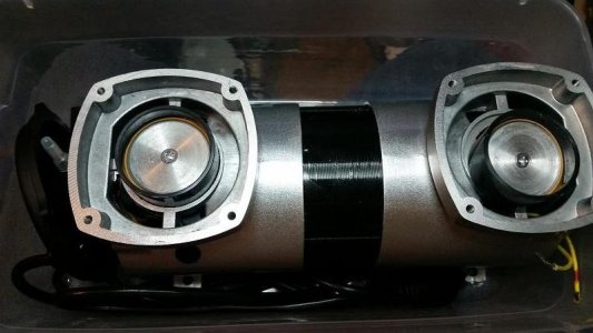
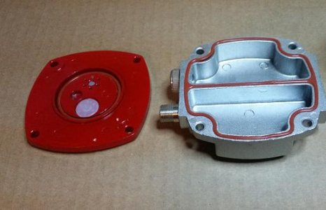
Now we were able to remove the heads, leaving the piston valves exposed, and then removing the valves you can see the piston walls/piston. Basically, these units have a two chambered head, one where the air comes in, and another where the air goes out, those are sealed against the valve, which is basically two check valves, one for allowing air to enter the piston chamber and one for allowing the air to exit the piston chamber. So the air inters the upper chamber, the downward motion of the piston creates a vacuum which sucks air through one of the check valves, then the piston moves upwards, creating pressure which forces the air through the second check valve, pressurizing the second chamber in the head. One could effectively turn this compressor into a cheap vacuum pump by simply installing the red valve plate backwards and not installing a check valve between the tank and compressor, so we need to be careful on re-assembly to ensure we do not install anything upside down or backwards. I put a black sharpie mark on the side of the head/valve/compressor assembly to ensure proper reassembly.

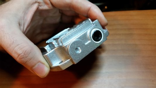
This is what the underside of the head and check valve plate look like.

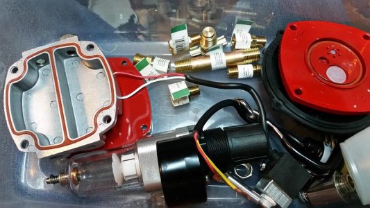
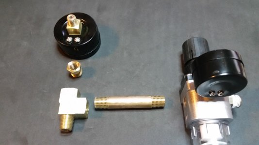
Lastly, I went out and purchased some of the parts I would need for the reassembly.
The next post will show the upcoming design, how we disassembled the old compressor, how we are cleaning/modifying the old tank, and maybe we can work on repainting it!

Also, sorry for the rather brisk descriptions for this first post, I didn't think I was going to do a worklog. That said, I will happily go into more detail on any specific thing, just ask if you need/want more!
 
Last edited:
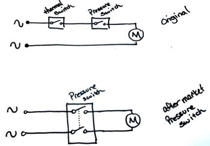
Very cool. Very serendipitous timing for me too, as I've just started an almost identical project (replacing the built-in pressure switch on my Badger 180-11 with an external one so I can properly use it with a tank), so it'd be cool to compare notes. In particular I'm very interested in how to properly adapt the wiring for the switch, as external switches use 4 wires + ground, whereas the internal one only has the 2 wires.
 
Nessus said:
In particular I'm very interested in how to properly adapt the wiring for the switch, as external switches use 4 wires + ground, whereas the internal one only has the 2 wires.
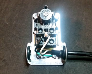
I don't think I am going to use an external pressure switch in this build, but having used one on my previous build, I might be able to give you a quick diagram of how they work. The only real difference is that they break both the hot and the neutral wire, instead of just the hot wire. (hence the 4 connections instead of 2).
The image with the actual switch shows the incoming wire from the wall, with both connections connected to line. Then simply have both wires (matching neutral for neutral and hot for hot) on the lower two connections marked "motor".

That should be all there is to it! If you have any other questions, don't hesitate to ask, and good luck on your project!
 
The next thing we need to work on is the tank that we are adding. The first step was to remove the tank from the old compressor setup and examine all the threads and look for rust damage and see what all we will need to do to make sure this tank will work.

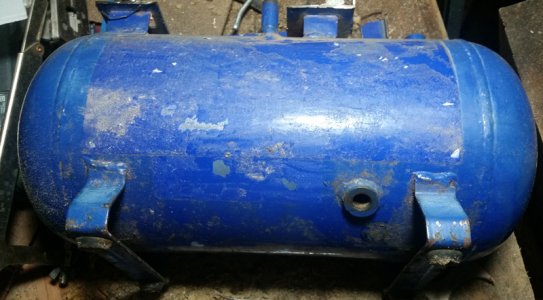
I removed all of the connections to the tank, the hose output, the drain cock, etc. There appeared to be some rust on the surface, particularly the legs (which is understandable) but using an inspection scope I found the inside did not appear to be too rusted. The tank was stored outside for a while, causing some condensation and thus some rust, but nothing major. None the less, we will add some rust inhibitor into the tank to make sure it does not rust further. I will also remove the stickers on the side and front.

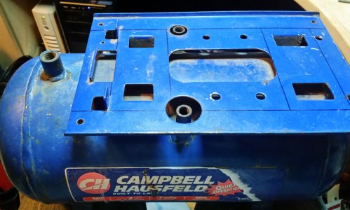
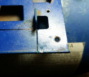
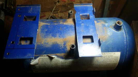
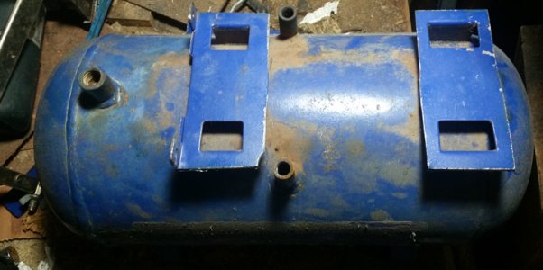
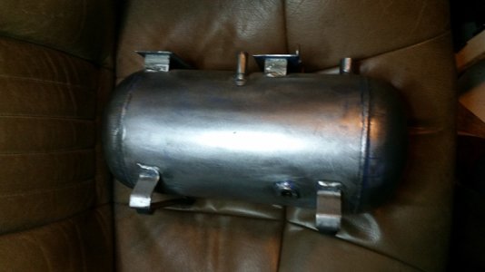
You will also notice on the top of the old tank, the landing platform has some black lines, this will be where I will be cutting the platform. I do not need all of the space on top, just the points for the legs, and removing the rest should improve the overall look of the finished compressor.

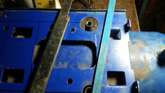
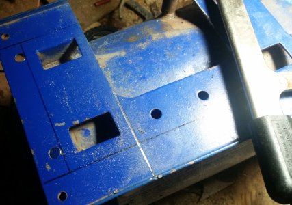
So I began using my hacksaw to cut along the lines I had made.
This method takes a while, but allows me to be extra careful when cutting to ensure my main cuts are accurate. My arms were tired but better to go slow and methodically for most of the cuts.

The middle and right sections off, I would not be able to cut the tabs off using a hacksaw without hitting the inlet connections, so it became necessary to use an angle grinder with a cutoff wheel for the remainder of the cuts.
From here, I used a heat gun and paint scraper to remove the old stickers on the side of the tank.
With that completed, there is only one thing left to do with the tank for now, but unfortunately it is raining today, so that will need to wait until tomorrow and hopefully it wont be raining. Here's a hint:
Right now I am going to work on some of the brass work/fittings and how I plan to arrange everything, and will make a post about that afterwards! :)
 
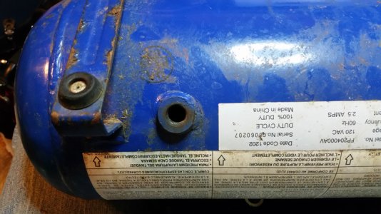
On to the brass. I decided to simplify the design as much as possible. I have four inlets/outlets on the tank. Two 1/4" NPT connections, and two 1/8 NPT connections. The bottom 1/4 one is specifically for the drain cock which we will not change. I purchased a new drain cock as a matter of course.

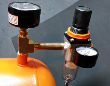
The 1/4 NPT connection on the top will be used as the output. I will use use a MFF 1/4 TEE connecting a 1/4 to 1/8 adapter so I can connect a PSI Guage for the tank specifically, then the tee will connect to a peice of 1/4 straight pipe 3" long, which will connect to the pressure regulator and moisture trap. It will be arranged as follows.
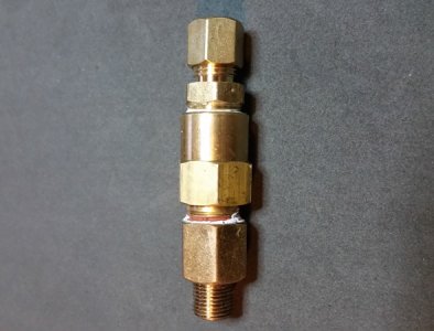
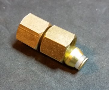
That leaves the two 1/8 NPT connections. One of them will have the Check valve connected to it, which will isolate the air and pressure in the tank from the compressor. Unfortunately the only check valve I could find with the specs I wanted was 1/4 NPT, and since I wanted to use compression fittings to connect it from the tank to the compressor itself, I needed to get a 1/4F to 1/8M adapter, as well as a 1/4 compression fitting. The check valve assembly looks like this:
The remaining 1/8" inlet will be used for both the pressure switch, and the safety relief valve. My old compressor had a 1/4" safety valve, so It became necessary to purchase a new 1/8 inch valve. It will be connected using a short 1/8" union, and a 1/8" FFF TEE. One side of the TEE will have the 1/8" pressure switch, the other side will have the 1/8" valve. Unfortunately I still need to purchase the TEE, and the pressure relief valve has not arrived from Amazon yet, so no photos for that part yet.

That is all of the tank connections, meaning the single compression fitting on the top of the check valve assembly is the only point where air can enter, which will be the point where the air from the compressor is connected.

The compressor itself had to be modified as well. The pressure regulator/check valve was previously connected to one side of one of the heads, so after removing it, it was necessary to plug that hole.

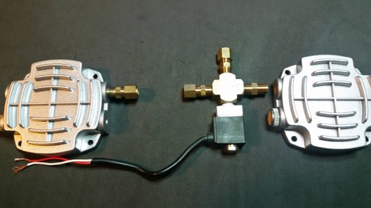
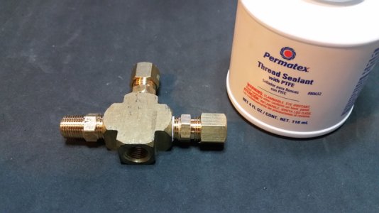
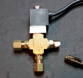
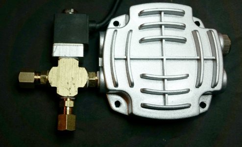
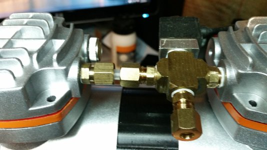
With that plugged, I could work on how the connection between the heads will be arranged. I decided to have a 1/8" cross tee which would allow me to use a short 1/8" union from one head, into the cross, then have a compression fitting both opposite and off to one side of the cross. Then I would be able to connect the unloading valve to the remaining connection of the cross. Finally I will use a 1/8" compression fitting in the remaining head, and use a short peice of tubing to connect the cross to the second head. The arrangement will be as follows.

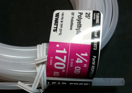
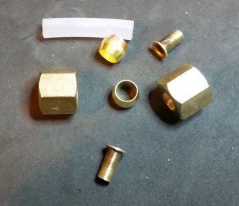
The compression fitting facing up in that photo will be connected to the tank using tubing. The tubing I purchased is this:

I've never used this type of tubing for this application, so at this point I am considering this an experiment! I will be using brass inserts and delrin compression fittings. The tubing came in a roll of 25' and I only need 1' or so, meaning I will have plenty of tries. If it does not seal well, I will try brass compression rings, if that does not seal properly, I will purchase 1/4 copper tubing instead. However, this tubing states that it works up to 140 PSI and this compressor/tank is regulated to turn on at 40 PSI and off at 60 PSI. The compressor does also have a secondary mode that bypasses the pressure regulator and will pump the tank up to 100PSI. However, none of this is anywhere close to 140 PSI, so I am hoping this stuff works well enough!

So at this point I am stuck until I can finish stripping and painting the tank, tomorrow I will work on assembling the compressor back together to the point that it is ready to be mounted onto the tank.

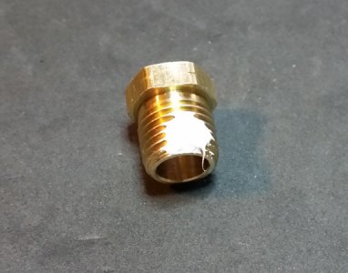
If anyone is wondering, I am using liquid thread sealant for this project. It is Permatex branded PTFE sealant. If you use this stuff (and I do love this stuff) you only need to put a dab on. You do not need to coat all the threads. Pipe threads are different than regular threads as they are conical in shape, meaning the two sides of the thread eventually touch, meaning the minute path that travels the length of the threads is extremely small, so you really only need the sealant at a single point for it to prevent leaks. There is no need to use a lot. The following picture is the kind I am using, as well as a photo of it after being applied to the threads. Even this amount is a bit more than necessary to be honest, but the threads are quite small and the brush you use to apply it is nearly twice the side of the fitting itself. lol

Alright, that is all for now. Hopefully the next post will include the stripping cleaning and painting of the tank! See you all next time!
 
I am no fan of home built compressors as few know what they are doing...But it is refreshing to see such a well laid out How To for those that do want to play.Even for those just interested in seeing the guts of a compressor.Nice work :) Be interested to see how it goes but do have a little question..Why not just put the reservoir inline? If you just want a buffer to stop the pulsing or overworking the little twin or is it more a looks thing to mount them together? An inline reservoir is handy to have as a separate element as then you can switch it in between various compressors, or bring it inside for quiet painting when the kids asleep and you just want that 30 minutes more painting time, especially in the future if your twin blows or not be used at all if you just have to pump up a tyre...
 
I am no fan of home built compressors as few know what they are doing...But it is refreshing to see such a well laid out How To for those that do want to play.Even for those just interested in seeing the guts of a compressor.Nice work :) Be interested to see how it goes but do have a little question..Why not just put the reservoir inline? If you just want a buffer to stop the pulsing or overworking the little twin or is it more a looks thing to mount them together? An inline reservoir is handy to have as a separate element as then you can switch it in between various compressors, or bring it inside for quiet painting when the kids asleep and you just want that 30 minutes more painting time, especially in the future if your twin blows or not be used at all if you just have to pump up a tyre...
Thank you for the kind words. I agree with you in not generally being a fan of home built compressor solutions, and it is usually cheaper to simply buy a compressor that comes with a tank than it is to try and mount a tank afterwards. You are also right that removing the regulator and simply running a hose from the old check valve to the tank then remounting the regulator on the tank would have been just as effective in nearly every way.

I will be using a secure but non-permanent mounting system, so if this compressor fails in the future I will be able to replace it with a new compressor. I suppose the reason for mounting it directly to the tank is primarily aesthetic, but also because this compressor is going to be used exclusively for airbrushing. I have a 24 gallon shop compressor in the garage that I use for other tasks like filling tires, using air tools or blowing the dust out of computer cases, so I don't really need this compressor to perform any kind of double duty. (that said, I do plan on having it set up that it is capable of doing additional tasks if it should become necessary.) I also have a limited amount of space where I can keep the compressor under the desk, which has more room vertically than horizontally. Lastly, I needed something that wouldn't wake family members at night like the shop compressor. I don't get home from the hospital until around 10:30pm, so if I want to do art it needs to be quiet enough to not disturb anyone who is already asleep.

Hope that answers your questions! :)
 
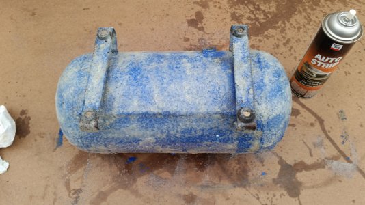
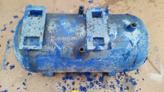
Alright, small update!! I had to replace the radiator in my fathers mini-van today, which took about 2 hours, so I got a late start, but I was able to strip the tank! Unfortunately it started raining shortly after I finished, so I was unable to get a coat of paint on, but then I am running low on rattle can's anyways, the only color I have a new can of is about the same color as the tank used to be, and I think I want to do something different. So I will take a trip to the hardware store in the next day or two and see what is available.

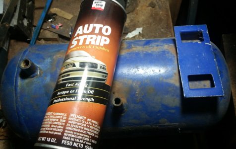
Let me start by saying that autostrip or any very strong paint stripper usable for automotive finish is highly caustic and you should absolutely use gloves and a respirator! You should also be in a well ventilated area, I did mine outside on a scrap piece of hardboard. Please be safe and follow all instructions on the can!


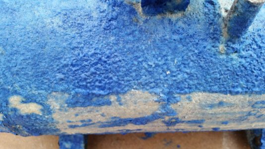
This stuff is really good, simply apply an even coat to the entire surface, and wait 10-30 minutes. The surface paint will bubble up as follows.
At this point you can begin to remove the old paint. For parts that had dirt or some other residue, or not enough stripper on you will need to re-coat them with stripper and wait another 10-30 minutes. After the first coat, the tank looked as follows.
There was some rust on the surface, probably from the few times I left the old compressor outside or in the garage, but it wasn't deep and should sand out. At this point, I did need to repeat the process on some areas and allow the stripper to work, particularly areas where there were stickers that had residue leftover, but after a second application those areas mostly scraped off as well.

After removing as much as I could using a rag and a razor, I used the garden hose with a narrow nozzle sprayer to get as high pressure as I could. This got off a lot of the paint, but also removed any remaining stripper, making the tank safe to hold with my bare hands.

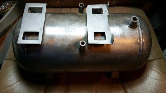
At this point there were lot of nooks and crannies that had paint, so I used a wire wheel on my drill to try and get a lot of the residual paint off. For finishing, I pulled out my electric sander with a 220 grit pad and some wooden planks with sandpaper glued on them. After about 10-15 minutes of using the electric sander I used my hands and the wooden planks with sandpaper to get into the nooks and crannies. Here is the final result of all that work!
I have a three day weekend next week, so I should be able to complete this project wed/thurs of next week! In the mean time, I will get the compressor prepped and post that progress in the next day or two.
 
I new it was just to have a cool looking compressor LOLOL..I want one too as am doing some markets of late.I only use mine when I paint inside cause it kinda fits under the desk LOL but have an airbrushed computer case here and and want to set up a mobile airbrush station out of it so will keep an eye on ya thread, may get some good ideas :)
 
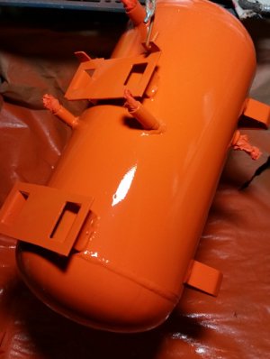
Quick update! I went to the store planning to get red paint, because I thought it would accent the red lines of the valves on the compressor, but then I felt like there are too many red compressor tanks in the world. I considered purple purely on the fact that I couldn't think of any brands that made air compressors in that color. I decided against that on account I wanted something different and personal. So... I went with the color of my Alma Mater, which just so happens to be the accent color of this website too!

I have one coat done, still have to sand a couple rough spots where dirt got on the paint plus a spot where something bumped the paint ( I let go of the rope by accident and it swung into the wall), and I had a single run that I will also sand down tomorrow, after the paint has cured more. Then one or two more more light coats and we should be good!

The plan is to paint the red edging of the compressor valves to match after reassembly.
 
Alright, continuing where we left off. The tank has been painted, and I even took the time to paint the edges of the red valves to match as an accent color. I've given the tank time to cure, so that the paint should be hard enough to let me start mounting things back together!

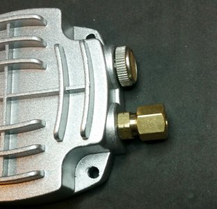
I began to start assembling the brass. In order to make the brass fittings seat as deep as possible without bottoming out, it was necessary to tap the heads and even the cross. There is not a lot of room between the heads, and having them seat as deep as possible gives me the 1/4" I need for connecting the two heads together.

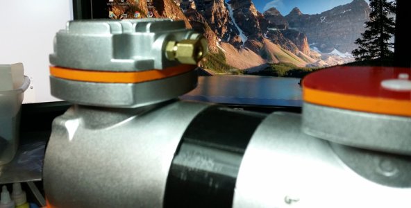
As you can see, they are seated almost flush with the head. (you can also see the accented orange on the edging of the valve plate). This was necessary because the two compression fittings would touch otherwise, I could have used a short piece of threaded pipe and connect the two together, but it would be necessary to remove both heads any time I needed to work on anything, this way I can remove each one individually if ever the need arises.

In order to connect the two heads together, I had to make a short union. To make it I had to use a dremel to shorten two brass inserts, then put all the pieces together so that the heads would seat nicely.

Once this piece was made, I could mock up the heads.

You can see how close those two compression fittings are with the hose between them. You might be able to tell that without seating the brass nice and deep those two pieces would have touched. This worked out good though, so at this point I could add the handles and bold the heads down.
 
Satisfied the tank has had enough time to cure, its time to get that tank ready for the compressor!

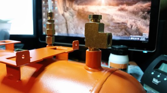
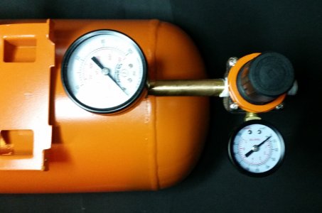
The first step to get the tank ready was to go ahead and mount the check valve, and mount the output TEE.
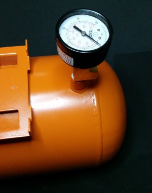
Once I added those two, I went ahead and added the gauge for indicating the tank pressure.
And with that mounted and secure, I could add the 1/4" pipe and pressure regulator back on. With the screwed on ring painted orange, of course!
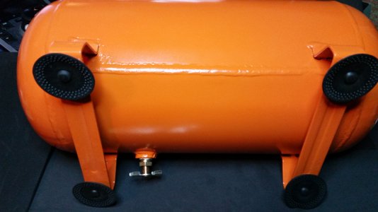
Alright, with that done, I could go ahead and put in the new drain cock on the bottom. You can also see the hole where the old feet were. In order to put in the new feet, I had to drill those out to a larger size.
I did that for all four feet, then added the new feet, which were the ones from the compressor itself, just moved from there to the tank.

With that done, the tank is just about ready for mounting the compressor!
 
Just a couple more things to do and we are just about finished!

First thing I did was set the compressor atop the tank to see what all I needed to do to get this completed.

Alright, you can see a couple things here, I have to feed that wire from the unloading valve through that grommet, then rewire it into the compressor. Next, you see that free 1/8" inlet at the bottom. I have ordered my relief valve, but it will not arrive until into February, and in order to get this thing set up and test it, I am going to skip adding the TEE with the pressure relief valve and the pressure switch (until the pressure relief valve arrives next month) and simply mount the pressure switch directly to that input. This will only be temporary for testing purposes (checking for leaks and making sure everything operates correctly).

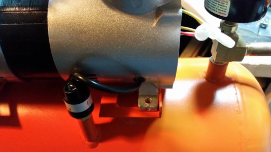
That said, the scariest part of my day was that I needed to drill a hole into my brand new compressor... On the bottom right area of that image. So, that was the next step, adding a hole and a new grommet. Then I put the compressor back on the tank, secured the pressure switch for now, and fed the wire through my new hole.
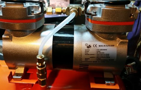
With this complete, I turned the tank around and added the hose running from the check valve to the compressor.
At that point, I could finish rewiring everything together, close up the compressor sides, and cut some foam padding for the compressor feet. Then its just tightening all the fittings down and we are just about finished!

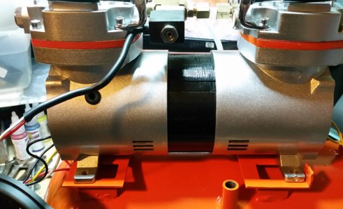
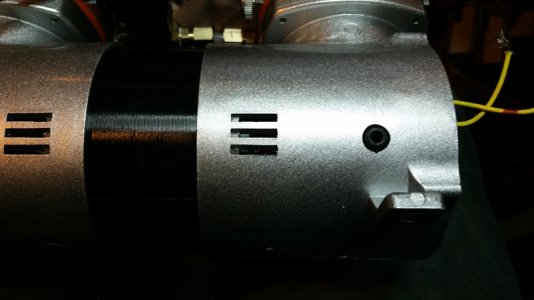
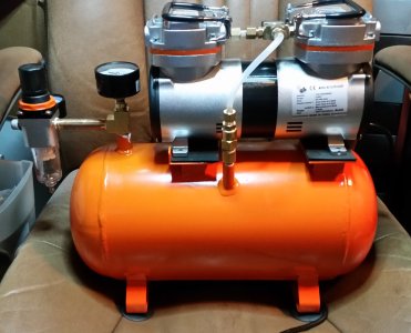
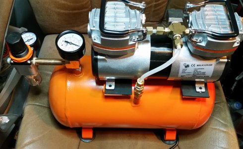
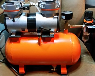
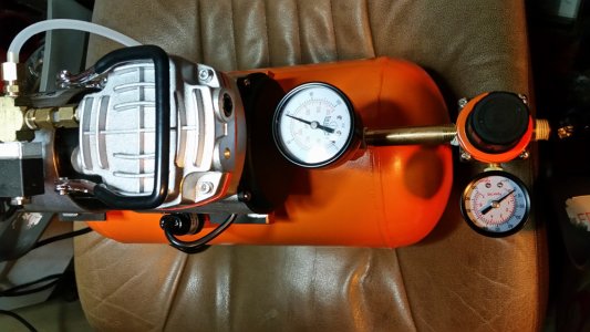
So, I went ahead and did all that, and here is what the compressor looks like after all that work!

You can see from those images that the tank does pump up to 60psi and cuts off as planned.

The only thing left to do is fix the tee when I get the valve, check for leaks and secure the compressor to the tank, which I still need to purchase some L-bolts to do that, but that will not really change the overall look and design of the compressor, so while I might add as a supplemental post, I think this worklog is pretty much done!

Thanks for your interest and thanks for taking a look!

As always, if there are any questions or something I did a poor job of explaining or seemingly glossed over for brevity, don't hesitate to ask!

Thanks again!
 
You've done a pretty professional job all in, I've seen a lot of homemade compressors that look like they gave a child a load of parts and let them loose on it, lol, you spent a lot of time making this look like to shop bought unit and I have to say I'm very impressed:thumbsup:

And the colour of the tank meets my approval;)

Do let us know your findings when you start using it, if it performs as good as it looks you'll be very chuffed and very proud I think:thumbsup:
 
Looks awesome and very nice job..looks super clean but is missing one major element....So needs Airbrushed...;) Well done and was a great result by the looks and will no doubt serve you well..Ya may of mentioned it in you thread but have you got a rough idea of the actual end costs, can't imagine it was too bad..
 
Madbrush said:
You've done a pretty professional job all in, I've seen a lot of homemade compressors that look like they gave a child a load of parts and let them loose on it, lol, you spent a lot of time making this look like to shop bought unit and I have to say I'm very impressed:thumbsup:
*blush* Thank you for the kind words!

RebelAir said:
Ya may of mentioned it in you thread but have you got a rough idea of the actual end costs, can't imagine it was too bad..
Oh, good question! I would say the total cost out of pocket was about ~50USD, most of that being in brass fittings, then some spray paint. There were some other costs, though couldn't give exact amount, for example I already had the sandpaper and stripper (always keep some on hand) so I didn't include that stuff in the cost, but it was still technically a cost. If I had to buy everything except the tank I would guess about ~75USD, and thats including paper towels, sandpaper, stripper, and denatured alcohol.

And, as you've both stated.. The next step will be testing it out with some airbrushes!! :laugh:
 
A few metrics I tested. Not sure how this stacks up to other peoples compressors, but here is what I found:

Paasche VL @25psi
can spray ~20s nonstop air before compressor turns on (60psi to 45psi)
can spray ~1m5s from 60psi to 25psi (just tank, compressor off)

Iwata HP-CS @25psi
can spray ~38s nonstop air before compressor turns on (60psi to 45psi)
can spray ~2m2s from 60psi to 25psi (just tank, compressor off)

Compressor
~31s refill from 45psi-60psi (without using airbrush)
from empty to 40psi ~1m 5s
from empty to 60psi ~2m 5s

Apparently the Paasche requires about twice the CFM than the Iwata. Didn't know it was such an airhog. Works good, but the Iwata is clearly the more efficient brush in terms of using air. o_O
 
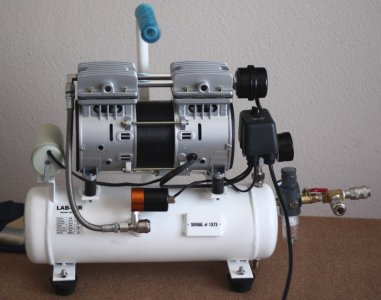
Really good job. On my compressor they fit stiff rubber tubing between the motor and the tank. It just isolates the motor away from the tank more. You can see it on the image below. The motor is a bit more powerful than yours so what you are doing could be enough.

Lab_air_compressor_02_sml.jpg
 
Thats a nice looking compressor Andre, thanks for sharing! I kind of like how high those risers are. It looks like they went for isolating the vibration of the compressor from the tank itself, instead of securing them together and isolating the vibration of the whole assembly from the ground.

I might add some additional vibration absorbing mechanism other than the foam, but Its already pretty quiet and the vibration is pretty low as it is. That said, I might come up with some kind of additional vibration absorbtion so that its possible for me to add a larger compressor in the future (ideally I would like a nice 1HP twin piston compressor).

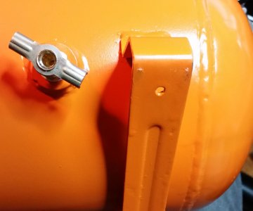
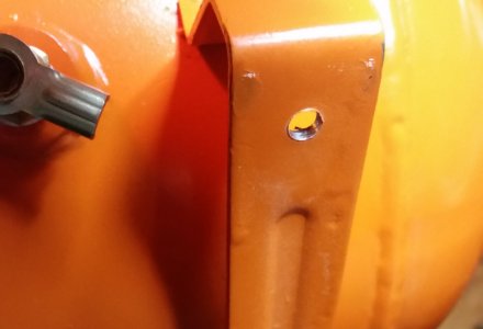
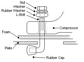
On the pictures you can see the large square openings on the remaining platform. Oddly enough, the holes on the compressor all end up in the outside most corner of all four of those square holes. Meaning they don't have any metal under the hole, so a regular bolt wont work, but since all of the holes line up beside the edge of the mounting plate, I can use an L Bolt, mount it to the compressor, set the compressor in place, then rotate the L Bolt so that the head rests under the plate, then tighten the bolt to secure the compressore. This diagram should help explain what I mean:
bolt_arrangement.JPG
 
Back
Top